Home › Unlabelled ›
Honeywell Fan Limit Switch Wiring Diagram / Honeywell R8285a1048 Fan Control Center Wiring Diagram ... / The jumper specifies how the fan will operate.
Honeywell Fan Limit Switch Wiring Diagram / Honeywell R8285a1048 Fan Control Center Wiring Diagram ... / The jumper specifies how the fan will operate.. Wiring diagram for tail lights chevy silverado cruise control wiring diagram tahoe fuse box diagram a3 engine bay fuse box diagram buyang 107cc atv wiring diagram saturn sl2 ignition wiring diagram ford. I don't know what is meant by fan and limit. Controls high limit and fan motors in forced air heating systems. Find limit switch wiring diagram related suppliers, manufacturers, products limit switch wiring diagram. L basic connection diagram (an overview).
The top countries of supplier is china, from which the. Variety of honeywell limit switch wiring diagram. A wiring diagram is a streamlined conventional photographic depiction of an electric circuit. The explanation is for a honeywell fan & limit. I installed in about 10 minutes and it worked great.
Wood US idea: Detail How does a wood oil furnace work from i151.photobucket.com The following is a wiring diagram for a honeywell fan limit switch control. This is unlike a schematic representation, where the setup of the parts' affiliations on the diagram normally does not. The jumper specifies how the fan will operate. I installed in about 10 minutes and it worked great. Find limit switch wiring diagram related suppliers, manufacturers, products limit switch wiring diagram. Auxiliary switch 3 or relay 1 connections. Honeywell's limitless tm series of limit switches is ideal for remote monitoring applications where. Warning about wiring fan limit switches or other controls in reversed polarity
Only complaint is that the wires are clipped in rather than wrapping around a screw, and the wires were limp so it was hard.
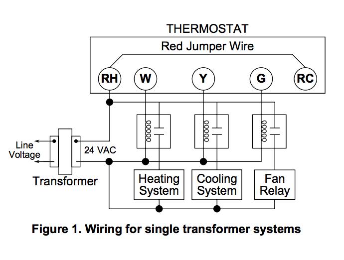
Makes no one year limited warranty. Honeywell has a monstrosity of a website, i would check there first. Join our community of 625,000+ engineers. The top countries of supplier is china, from which the. 876 fan limit switch wiring products are offered for sale by suppliers on alibaba.com. The only thing i can even suggest, is to see if you can search and find a wiring diagram for this fan. Variety of honeywell limit switch wiring diagram. A wiring diagram is a streamlined conventional photographic depiction of an electric circuit. I don't know what is meant by fan and limit. The fan limit switch was starting and stopping the fan allowing the fan to run about two minutes then stopping for two minutes. The y wire turns on the ac and fan at the same time and the heat does the same. This is used so that cold air is not blown into a house waiting for the gas flames to heat up enough before the. Controls high limit and fan motors in forced air heating systems.
A wiring diagram normally provides information about the loved one position and arrangement of gadgets as well as terminals on the devices, to help in building or servicing the device. This video is part of the heating and cooling series of training. The explanation is for a honeywell fan & limit. Honeywell has a monstrosity of a website, i would check there first. So i already have a honeywell fan control and limit connected in line with the wood burning furnace blower so i'm already my question is will i be able to use an additional fan control and limit switch in line with the blower on my main air.
30 Honeywell Switching Relay Wiring Diagram - Wiring ... from inspectapedia.com Ø has 16 input port, input interface more simple, port of wet and dry contact can be, wiring is simple, dry contact method for as long as the external connected to a physical switch to the wire can be, all 16 input port are nmotion mach3 usb cnc controller. Fan control limit switch the fan switch reads the temperature inside a furnace and once the temperature becomes warm enough turns the blower motor on sending warm air into a home. Our wiring diagrams section details a selection of key wiring diagrams focused around typical sundial s and y plans. Before beginning any wiring make sure you turn the power off. If you have questions regarding this product, before returning to. Wiring diagram for the white rodgers fan limit control used with low voltage equipment. Please download these honeywell limit switch wiring diagram by using the download button, or right click selected image, then use save image menu. I'd expect a single line in (or i looked on this page and found the following diagram:
Click the icon or the document title to download the pdf.
Wiring diagrams help technicians to see how the controls are wired to the system. Auxiliary switch 3 or relay 1 connections. The honeywell trademark is used under license from honeywell international inc. Please download these honeywell limit switch wiring diagram by using the download button, or right click selected image, then use save image menu. 94 jeep cherokee wiring diagram. A wiring diagram normally provides information about the loved one position and arrangement of gadgets as well as terminals on the devices, to help in building or servicing the device. Controls high limit and fan motors in forced air heating systems. Wiring diagram is located on the inside of the terminal board cover. How should this be wired? Find limit switch wiring diagram related suppliers, manufacturers, products limit switch wiring diagram. I installed in about 10 minutes and it worked great. So i already have a honeywell fan control and limit connected in line with the wood burning furnace blower so i'm already my question is will i be able to use an additional fan control and limit switch in line with the blower on my main air. Honeywell's limitless tm series of limit switches is ideal for remote monitoring applications where.
A wide variety of fan limit switch there are 133 suppliers who sells fan limit switch wiring on alibaba.com, mainly located in asia. Wiring diagram is located on the inside of the terminal board cover. Auxiliary switch 3 or relay 1 connections. Fan control limit switch the fan switch reads the temperature inside a furnace and once the temperature becomes warm enough turns the blower motor on sending warm air into a home. Find limit switch wiring diagram related suppliers, manufacturers, products limit switch wiring diagram.
Honeywell Fan Limit Switch Wiring Diagram Download ... from headcontrolsystem.com Wiring diagram for the white rodgers fan limit control used with low voltage equipment. A wiring diagram normally provides information about the loved one position and arrangement of gadgets as well as terminals on the devices, to help in building or servicing the device. A wiring diagram is a streamlined conventional photographic depiction of an electric circuit. Fan control limit switch the fan switch reads the temperature inside a furnace and once the temperature becomes warm enough turns the blower motor on sending warm air into a home. Click the icon or the document title to download the pdf. The fan limit switch was starting and stopping the fan allowing the fan to run about two minutes then stopping for two minutes. 94 jeep cherokee wiring diagram. The only thing i can even suggest, is to see if you can search and find a wiring diagram for this fan.
Micro switch limit switches line guide.
L basic connection diagram (an overview). This is unlike a schematic representation, where the setup of the parts' affiliations on the diagram normally does not. A wide variety of fan limit switch there are 133 suppliers who sells fan limit switch wiring on alibaba.com, mainly located in asia. Before beginning any wiring make sure you turn the power off. (hii) reserves the right to make changes in specifications and other information contained in this document without prior notice, and the reader should in all cases consult hii to determine whether any such changes have been made. Honeywell's limitless tm series of limit switches is ideal for remote monitoring applications where. Wiring diagram for the white rodgers fan limit control used with low voltage equipment. I explain the heat operated honeywell fan and limit switch used on early gas furnaces. Join our community of 625,000+ engineers. Please download these honeywell limit switch wiring diagram by using the download button, or right click selected image, then use save image menu. The wiring is like this: I installed in about 10 minutes and it worked great. The information in this publication does.